Block Diagram C Arm Machine Parts

Janome 380 381 Sewing Machine Service Manual Manual Includes Removal Of Top Cov Sewing Machine Service Sewing Machine Service Manuals Sewing Machine

Singer 421 Slant O Matic Sewing Machine Instruction Manual Sewing Machine Instructions Sewing Machine Instruction Manuals Sewing Machine

Kenmore 158 16410 Sewing Machine Instruction Manual Sewing Machine Instructions Sewing Machine Instruction Manuals Sewing Machine

Milling Machine Parts And Their Function Milling Machine Parts Milling Machine Milling

Kenmore Model 385 17126690 Sewing Machine Service Manual Sewing Machine Service Manuals Sewing Machine Service Sewing Machine Manuals

How To Thread My Sewing Machine Sewing Machine Sewing Kenmore

Let us simplify reduce this block diagram using the block diagram reduction rules.
Block diagram c arm machine parts.

Singer 9910 Quantum Sewing Machine Manual Sewing Machine Manuals Sewing Machine Sewing

Coats 20 20 Air Flate Parts Panzitta Sales Service

White 503 534 Superlock Sewing Machine Service Manual Sewing Machine Service Sewing Machine Service Manuals Sewing Machine

Reprint Of C P Chandler And Price Letterpress Parts By Javaphoto 9 99 Letterpress Machine Letterpress Letterpress Printing

Necchi 4795 Sewing Machine Instruction Manual Sewing Machine Instructions Sewing Machine Instruction Manuals Sewing Machine Manuals

Diagram Of V Bed Knitting Machine Machine Knitting Knitting Textiles Fashion

Block Diagram Of R Vsm A Head B Electromagnet C Pick Up Coils D Hall Sensor E Capacity Sensor Of Samp Electromagnet Block Diagram Control System

Singer 4423 Sewing Machine Instruction Manual Sewing Machine Instruction Manuals Sewing Machine Instructions Sewing Machine Manuals

Pin On Ar 15 Lower Parts Kit
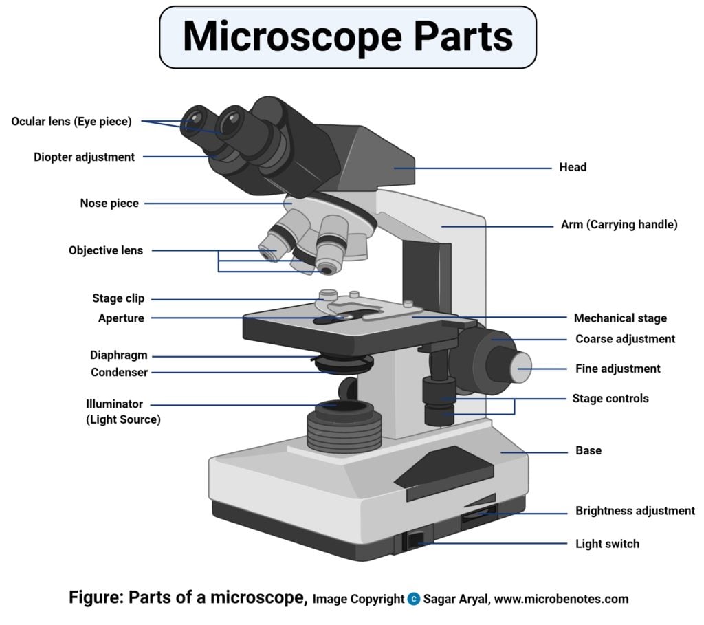
Parts Of A Microscope With Functions And Labeled Diagram

Staggering Useful Ideas Car Wheels Wallpaper Car Wheels Diy Kids Car Wheels Holder Car Wheels Chevy Cama Automotive Mechanic Car Maintenance Automotive Repair
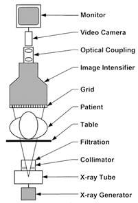
Modern Fluoroscopy Imaging Systems Image Wisely

Morse 4400 Sewing Machine Instruction Manual Sewing Machine Instruction Manuals Sewing Machine Instructions Sewing Machine Repair

Dressmaker 2402 Sewing Machine Threading Diagram Sewing Machine Dressmaker Sewing Machine Dressmaking

Viking Husqvarna 21e Sewing Machine Instruction Manual Sewing Machine Viking Sewing Machine Sewing Machine Instruction Manuals

Brother Xl731 Sewing Machine Instruction Manual Examples Includes Knowing T Sewing Machine Instruction Manuals Brother Sewing Machines Sewing Machines Best

Janome 2030dc Xl601 Sewing Machine Service Parts Manual Sewing Machine Service Sewing Machine Machine Service
Your Source For All Your Aircooled Vintage Vw Parts Vw Engine Vw Beetle Parts Volkswagen Cc
Https Encrypted Tbn0 Gstatic Com Images Q Tbn 3aand9gcrkuolnb2yy7il38ccmkekqpygq 14duaguqqtpbcq Usqp Cau

1937 216 Cid Chevy Engine Chevelle Parts Mustang Parts Chevy Trucks

Kenmore 158 18130 158 18131 Sewing Machine Manual Sewing Machine Manuals Sewing Sewing A Button

Typical Block Diagram Showing Working Of Speech Recognition System Speech Recognition Speech Recognition

Kenmore 12332 Sewing Machine Instruction Manual 385 12332 Sewing Machine Instruction Manuals Sewing Machine Sewing

Shredder Line Drawing Recycling Machines Shredder Machine Paper Shredder
Source : pinterest.com
